Pre-Compiled miniThrottle Relay
miniThrottle: A model railroad WiFi throttle.
What is it?
It is a pre-configured and pre-compiled version of miniThrottle set to operate as a DCC-Ex relay. There isn't a precompiled version of miniThrottle as a throttle only at this stage. Calling it prebuilt is a bit of a misnomer as it is not a ready-to-run option. It is a pre compiled image. You still need to source your own hardware and assemble it yourself. But the firmware is ready to install, and assembly follows a recipe. As such it can be installed on a specific hardware configuation, which then allows:
- Installation on a Esp32 module with built in SDD1306 display. Only this module is supported by the pre-compiled software. (see section below on physical connections for detail)
- Serial connection to DCC-Ex. DCC-Ex does not require compiling with WiFi support, but no issues if it does have it.
- Relay up to 8 WiThrottle throttles (eg Engine-Driver or other miniThrottle throttles) to DCC-Ex.
- Local throttle with 4x4 keypad and potentiometer
- Configurable usng either USB serial connection or web-browser
The local throttle controls are optional, but may be useful in situations where you are attempting to run DCC with a minimum of additional "stuff". Where the additional "stuff" may include addional physical boxes and wired interconnects or simply installing a mobile phone app.
Note: This pre-compiled version is not suitable for a stand-alone / hand-held WiFi throttle. However it may work as either a relay and/or a tethered throttle.
While it is possible to connect the module directly to DCC-Ex, this is not recommended. Mounting the module on an Arduino prototyping board, requires slightly more effort and allows the module to be stacked on DCC-Ex.
If you wish to run on an alternative hardware selection or with different options then you may still compile from source code.
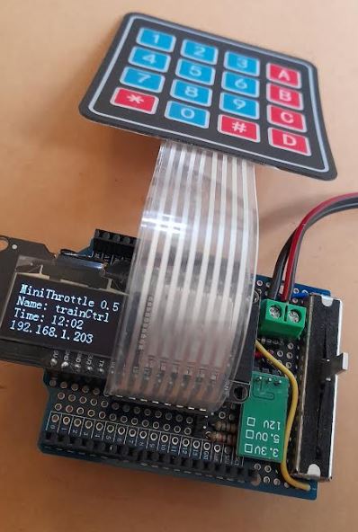
The example on right shows a precompiled miniThrottle unit incorporating a 5V buck converter which allows the miniThrottle and DCC-Ex to be driven by the same 12 or 15 volt power supply as the trains. This is built on a prototyping-hat that can be seated on top of your DCC-Ex modules.
Install a Pre-Compiled miniThrottle System
As a precompiled version, no compiler / Arduino-IDE is required. Some downloads are required as indicated below. And the Esp32 module is connected via a USB cable in order to flash the precompiled image to it.
By downloading from this site you accept the conditions of use.
- Start by downloading the ESP flash download tools. If you don't already have these and unzip the file to your pc. Note these tools are only available for Windows systems.
- Download the pre compiled image and unzip to a working directory.
There are 3 variants of relay available as precompiled images as indicated below.
This should contain files with memory location in their names which we will use at a later stage.
NB: These images are still in testing use at own risk, some functions may not work:File Name Save At Function miniThrottle_bin/0x1000_bootloader.bin 0x1000 Boot loader miniThrottle_bin/0x8000_partitions.bin 0x8000 Partition table miniThrottle_bin/0xe000_ota_data.bin 0xe000 Over The Air (OTA) update data miniThrottle_bin/0x10000_miniThrottle.bin 0x10000 Program code
zip File Description Comments miniThrotPreBuild.zip Relay with local controls Display, Keypad, Potentiometer
Local controls
Up to 8 relay clients
Web configurable
programming track accessible though local controlsminiThrotPreBuildNoCtrl.zip Relay with local display and no controls Display only
Display shows status info
Up to 8 relay clients
Web configurableminiThrotPreBuildNoDisp.zip Relay with no local interface No local interface
Up to 8 relay clients
Web configurable
May work with many Esp32 modules but only expected to work for the unit as shown here - Connect the Esp32 module to your PC using a USB cable.
- Go to the folder containing the ESP flash download tools, and run the application. This opens both a control and a status window. The control windows are discussed below.
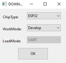 In the window select processor type of ESP32, and develop mode.
Factory mode would allow you to perform the install on to multiple units simultaneosly.
In the window select processor type of ESP32, and develop mode.
Factory mode would allow you to perform the install on to multiple units simultaneosly.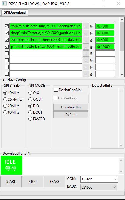 Now using the elipisis button next to the file names select the files you want to write to the Esp32 module.
Note if the option is unchecked in the left column then that image file won't be written to the module.
Copy the file location to the @ location.
Other settings to look for are
Now using the elipisis button next to the file names select the files you want to write to the Esp32 module.
Note if the option is unchecked in the left column then that image file won't be written to the module.
Copy the file location to the @ location.
Other settings to look for are- SPI Speed = 40MHz
- SPI Mode = DIO
- Com port to match your USB com port
- Speed = 921600 or less
Once set you should be able to select start to flash the image to the module. The status window should show details and give an indication of progress. Once compete a blue Finished indicator will appear in the control window, and you can close the ESP tools window(s).
After the image is burnt to the module, you should boot it before typing to access it. You will be able to access it using either the serial port (say using putty or TeraTerm terminal emulation) or using a web browser. Initially it on't have details of your local network, but the module will initially presnt a "dccStation" network which you can join. On this dccStation network connect to http://192.168.4.1 and if prompted for a password, your initial user is "admin" with a password of "secret". (without the quotes in either user name or password.)
Physical Connections
The module used can found by searching Google (or other search engines) using the term "esp32 oled", and purchased from AliExpress, Ebay, Amazon etc.
| Left Hand Side | |
|---|---|
| Pin(s) | Usage |
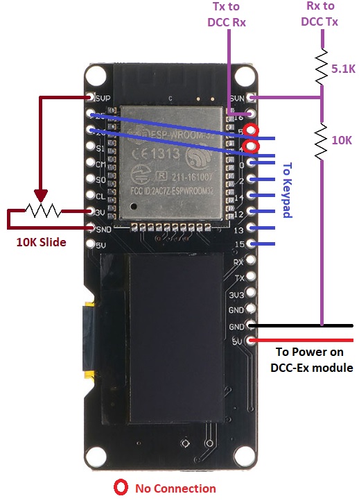
| 36 / SVP | 10k - 20k potentiometer centre / slider, pot pin 2 (any linear potentioneter in this range should be OK.) |
| 25, 26 | 4 x 4 keypad, membrane type recommended, same keypad as pins 0, 2, 14, 12, 13 and 15. |
| S1, CM, SO, CL | no connection - used to access internal memory |
| 3V | potentiometer high / fast side / pot pin 3 |
| GND | potentiometer low / slow side / pot pin 1 |
| Right Hand Side | |
| Pin(s) | Usage |
| SVN, 39 | RX connect to DCC-Ex TX pin (via 5K resistor to DCC-Ex and 10K resistor to GND) |
| 16 | TX connect to DCC-Ex RX pin |
| 5, 4 | no connection - used by I2C connection of display |
| 0, 2, 14, 12, 13, 15 | 4 x 4 keypad, membrane type recommended, same keypad as pins 25 and 26. |
| RX, TX | no connection - same console connection as USB serial |
| GND | Connect DCC-Ex GND, common ground |
| 5V | 5v supply from DCC-Ex |
Note: If using this as WiFi relay only (ie no local controls) then the potentiometer and keypad connections are left disconnected. In this case you don't need a module with a display, as long as pins SVN (39) and 16 are available to connect to the DCC-Ex module.
In the config.h file of CommandStation-EX, you may want to check the following and reflash the CommandStation-EX module:
- Disable WiFi support unless you still want to use a WiFi module in addition to miniThrottle.
#define ENABLE_WIFI false
- Enable one or more additional serial interfaces. Connect to these and the main USB interface's use won't conflict with miniThrottle, and/or allow multiple miniThrottles/other-serial-throttles to connect.
Note through if you use a WiFi module leave that interface commented out / disabled.
//#define SERIAL1_COMMANDS
#define SERIAL2_COMMANDS
#define SERIAL3_COMMANDS
First Time Use
Time to customise the unit!
You can configure the unit either via web page or connecting to the serial port. The serial port parameters are 115200 (speed), 8bits, no parity, 1 stop bit and no flow control. On a PC you need a terminal emulation such as Putty or TeraTerm-Pro and a USB cable attached to the miniThrottle device. It is assumed that for most users the web page will be the best option. However, the serial port option can still be useful if you have forgotten the admin password.
On the first start the unit should run an unsecured access point called "dccStation". No password is required. Connect to this access point and use your web browser to go to http://192.168.4.1. To access anything other than the status page you will need an admin password. This is initally a user of "admin" and a password of "mysecret", neither of which contain either quotes or capital letters. Now work through the various options to customise your miniThrottle device. See the web interface configuration page to review details, but here are some general comments.
- Be security aware, but not totally paranoid.
- Change the admin user name and at the very least the initial password. Anyone who has read this page knows the initial credentials! (admin/mysecret)
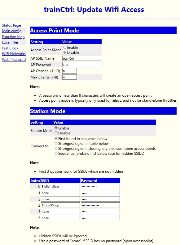
- Configure the network. It is recommended that you use the unit in either Access-Point mode or Station-Mode but not both. But the unit is capable of running both Access-Point and Station mode. If operating as an Access-Point, do set your Access-Point password. Unless of course you're OK with any passer-by connecting to it. You can also restrict the number of workstations connecting to your Access-Point.
- The main config can be use to set your unit's name, rotate the display, select either standard or bidirectional mode driving, etc
- Use the files section to define your locomotive roster and turnouts.
The Keypad
There are 2 modes of keypad operation: menu mode and driving mode. Driving mode is used when contolling a locomotive.
Menu mode
The numeric keys can be thought of as acting as a directional control / arrow keyad, except when entering numbers such as a loco address. In this mode:
| Keys | Function |
|---|---|
| 2, A | Go up one option |
| 8, B | Go down one option |
| 4, C | Go to previous menu, or if at top menu refresh display |
| 6, D | Go into selected option |
| 5, # | Go into selected option |
Note potentiometer is ignored in menu mode.
Driving Mode
| Keys | Function |
|---|---|
| 0 - 9 | Functions 0 - 9 |
| A | Speed up |
| B | Speed down |
| C | Forward |
| D | Reverse |
| * | Engage/Disengage potentiometer (allows keypad-only control) |
| # | Locomotive menu, when speed is zero |
In standard driving mode the extremes of the potentiometer represent stop and full speed. In bidirectional mode the potentiometer center position represents stop, while the extremes represent full speed in either forward or reverse.
Changing direction of a moving train will stop it.
The locomotives selection option is not expected to display if there is no track power. If it does not appear after applying power, you may need to refresh the menu using the back button, either 4 or C.
When removing locomotives in an in-throttle consist, you can only remove the lead loco if it is the last locomotive in the consist.
| Thank you for visiting camelthorn.cloud | Home |