Physical and electrical connections for HydraFerret modules
Introduction
At the heart of a HydraFerret module is a ESP32 processor. This needs a power source, and various sensors to monitor. Once wired up it connects wirelessly to a local network, which passes the measured data to a xymon server. The xymon server may be local or remote. This section covers some of the considerations for getting the unit physically installed. A description of the electrical connections to wire the esp32 module and the sensors together is also discussed. The process to get firmware installed on the ESP32 module is covered elsewhere.
Output Pin Usage
HydraFerret assumes you have a plan of how pins are used, as it won't check for pin contention. Therefore, it is recommended you create a spreadsheet of pin usage for your module. Note sometimes modules with built in SDD1306 display use pins 4 and 5 for I2C. Generally though you can map any pin to any function, but avoid remapping console and SPI memory pins. ADC input pins can also be used for digital input if required.
The following table can be used as a spreadsheet template to track the 40 general purpose I/O (GPIO) pins of a esp32 processor. Note the actual chip has 49 connectors (48 pins and the base), and the remaining pins are used for power, timing etc.
| Pin | Project Usage | Comment | Pin | Project Usage | Comment |
|---|---|---|---|---|---|
| 0 | Boot issues if held low at boot | 20 | |||
| 1 | Console Tx | Console Transmit | 21 | ||
| 2 | Sometimes built-in LED | 22 | |||
| 3 | Console Rx | Console Receive | 23 | ||
| 4 | Sometimes I2C SCL | 24 | |||
| 5 | Sometimes I2C SDA or built-in LED | 25 | |||
| 6 | Do Not Use | Used for SPI Memory | 26 | ||
| 7 | Do Not Use | Used for SPI Memory | 27 | ||
| 8 | Do Not Use | Used for SPI Memory | 28 | ||
| 9 | Do Not Use | Used for SPI Memory | 29 | ||
| 10 | Do Not Use | Used for SPI Memory | 31 | ||
| 11 | Do Not Use | Used for SPI Memory | 32 | ADC input | |
| 12 | Avoid for input | 33 | ADC input | ||
| 14 | 34 | ADC input | |||
| 15 | 35 | ADC input | |||
| 16 | 36 | ADC input, input only | |||
| 17 | 37 | ADC input, input only | |||
| 18 | 38 | ADC input, input only | |||
| 19 | 39 | ADC input, input only |
Power source
If powering the unit using USB supplied power, eg from a computer or "wall-wart", then most of the hard work is done, and the ESP module and sevral sonsor modules can work from this. But what if you are powering from a higher voltage source? It is assumed the higher voltage will be some direct current source such as a car battery or a solar panel. If powering from alternating current such as main power, a transformer and rectifier or switching power supply would be needed.
If the voltage source is much higher than 5V then do not connect this directly to the ESP32 module. While it is true the modules generally come with a voltage regular that can withstand 15v input, this regulator needs to drop the voltage down to 3.3V. If the module output is 100mA, then the input current will be about the same, which means most power in the system will be lost as heat! In this example if using 14.5V from a "12V" Solar charger battery under full charge, 11.2V is wasted. At a 100mA load, that is 1.12 Watts wasted, and 0.33 Watts of useful energy! (77% waste)
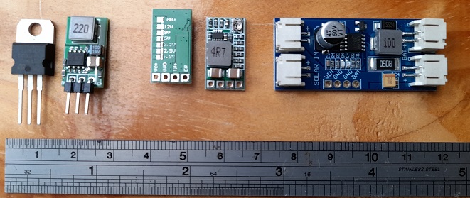
The answer to this problem is to use a "buck-converter" to reduce the voltage. While not 100% efficient, these are much more efficient than just wasting power through a voltage regulator. Typically these will contain some sort of coil and an ocillator. In simple terms they can be considered a form of step down transfomer. In the photo below we can see some options, from left to right:
- 7805 (5V) regulator chip. Such solid state regulators are fine if all is required is to step down a few volts or to have a precise voltage.
- A buck converter equivalent of the 7805 regulator. this will be more efficient when dealing with higher voltages, its input Wattage (power) will closely match its output wattage (ie: Watts = Volts x Amps). The coil is the component marked 220.
- A buck converter, with selectable output voltages which require theconnection of the solder tabs on the left of the unit to select the output volatage. Only one pair of solder tabs should be selected.
- Same as 3, but showing component side of the module. The coil is the component marked 4R7.
- A solar charger unit, with solar panel inputs on the left and battery / circuit output on the right. Depending on the amount of direct sun light reaching the panel and the current draw (including battery re-charge) the voltage will vary between 0V and Voc (Voltage with open circuit / no load max voltage). The charge must be able to withstand the open circuit voltage. The buck converter coil in this instance is marked 100.

Wiring components together

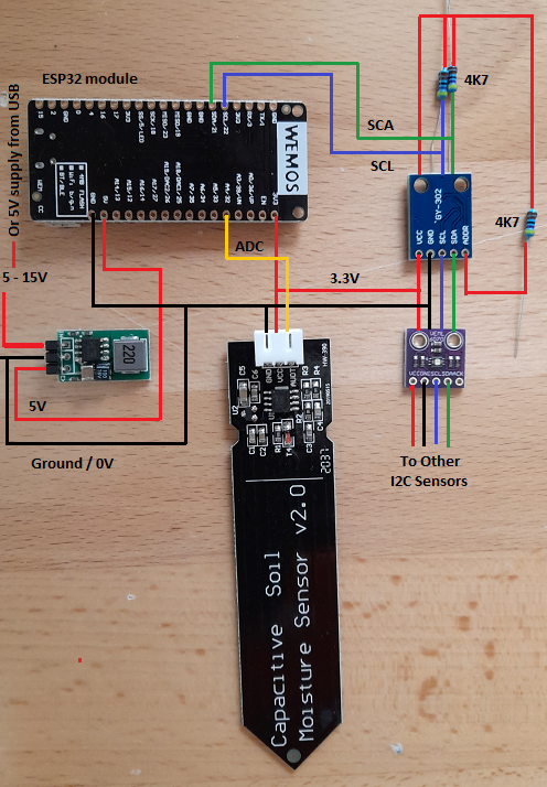
For this section consider the diagram to the right. The interconnections between components are colour coded.
- Red - Positive power supply. Note the power can vary and might be the 14.5v that a solar powered deep cycle battery may be providing, or 5v USB power levels or 3.3v CPU power. Many sensors also use 3.3v power, but some may require 5v. An axample of a 5v sensor is a PMS-5003 particulate sensor which requires 5v to power an internal fan.
- Black - Common ground / earth or 0v: This is the common voltage reference for all devices in this circuit.
- Yellow - Analogue output which connects to the internal analog to digital (ADC) of the ESP32. Up to 8 ADC inputs can be connected.
- Blue - i2c bus clock signal: this provides the timing signal of the i2c bus. Multiple sensors can connect to the i2c bus. HydraFerret supports up to 2 i2c busses.
- Green - i2c bus data signal. Only one device at a time can place data on the i2c bas at any time, and the ESP32 module acts as the master (or controller) of the bus. It will coordinate signals from devices.
- Not shown - counter input: this counts pulses on an input, such as from Hall effect magnetic counters in water flow meters. Up to 8 such counters may be defined on a HydraFerret module.
- Not shown - OneWire bus: this allows temperature sensors such as ds1820 to be connected. Multiple ds1820s may be connected in up to 4 OneWire busses.
Bus Configuration
i2c (two wire) and OneWire busses need a pull up resistor. Often a resistor in the 3k9 - 4k7 range is used. Lower values will result in a slightly higher current draw, but provide a sharper response. It may be necessary to use a lower pull up resistor where longer cable runs are needed and there may be more line capacitance to deal with. When communicating over i2c active devices will pull the bus to ground, otherwise they are left "floating". The pull up resistor will pull the signal to a high value, therefore these resistors should connect to the 3.3V positive. Connecting them to 5V (even if there are 5V devices on the i2c bus) will result in an over-voltage condition which may damage the processor.
On i2c busses the pull up resistors connect to both the clock (marked SCL, CL or CLK) and data (marked SDA or DA) inputs. For onewire busses it will be connected to the data line. Only one pull up reistor per line per bus is required. Don't add an additional pull up resistor per sensor. i2c is good for relatively short distances of up to a few meters (or yards), where as OneWire may run to 10s of meters (or yards).
HydraFerret allows up to 2 i2c busses, and 4 OneWire busses. This allows cabling to run in opposite directions from the HydraFerret module, and in the case of i2c have devices with the same address on either bus. It is possible to configure the unit without either bus.
HydraFerret does not (at this stage at least) support passive mode on OneWire bus. In passive move devices only need a ground and data connection, and sensor power is supplied over the data line. OneWire devices connected to HydraFerret require both positive and ground power in addition to the data signal.
Counters
The counters act as a pulse counter and may be used to connect water flow meters to the HydraFerret device. Using a multiplier allows the pulse count to be converted to litres (or gallons) or left as a raw count.
Analogue to Digital Conversion (ADC)
The input levels should never exceed to 3.3V power supply of the processor. If necessary to ensure this use a pair of resistors as a voltage divider such that the voltage input never exceeds the CPU power. As input voltages are sometimes expected to be much lower than this level the ADC may be configured using attenuation levels to boost ADC sensitivity.
Serial Busses
The ESP32 supports up to 3 serial interfaces. Since one is used by the console, this leaves 2 interfaces for other data. The input (RX) signal should never exceed the CPU supply voltage. If required provide isolation from RS232 level using an opto-coupler, or use a resistor pair as a voltage divider to attenuate the signal.

Outputs
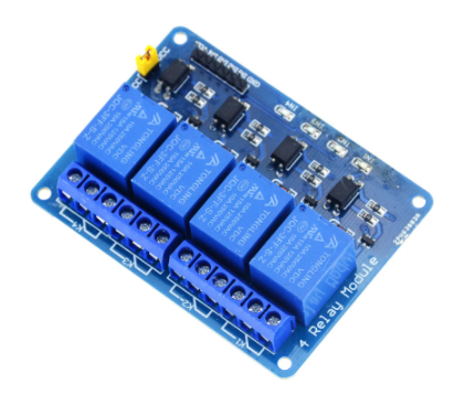
HydraFerret allows up to 8 outputs to be defined. These are 0V for off or 3.3V for on. As the CPU has limited output wattage, these outputs would need to connect to a transistor or opto-coupler in order to drive a higher powered load. The combined output wattage should be kept below the total CPU wattage. Allow for CPU power required during wireless transmission too. Many relay modules come with opto coupler which will not only limit the output wattage to acceptable levels, but provide isolation to the modules supply voltage which may be as high as 5V or 12V.
An exmple of a 4 channel relay module with opto-coupler is shown on the right.
Other Considerations
When using in-ground sensors such as the soil moisture sensors using a capacitative sensor such as that shown in the wiring diagram above is preferred. Sensors with bare electrodes are OK if used as flood sensors where exposure to moisture is expected to be rare. Otherwise these will fail after a period of time when the probe corrodes due to to electrolysis. For sensors such as that shown in the diagram, a coat of paint (quick drying enamel nail-polish?) over the electronics should also proctect them from moisture exposure. A paint coating around the circuit board edge may also prevent circuit-board fibres wicking any moisture. Do not paint over the sensor part.
| Thank you for visiting camelthorn.cloud | Home |